友谊中心医院门诊大楼设计毕业论文
2020-02-17 00:26:23
摘 要
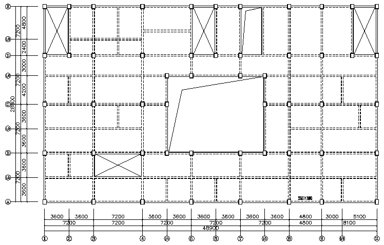
本毕业设计题目为友谊中心医院门诊大楼设计,属于多高层钢筋混凝土框架结构。本设计需要进行建筑设计和结构设计,完成该工程的主体结构计算,以及绘制相关建筑和结构施工图。
建筑设计部分参考相关规范、图集,并结合选题进行,完成建筑平立剖及建筑构造设计。
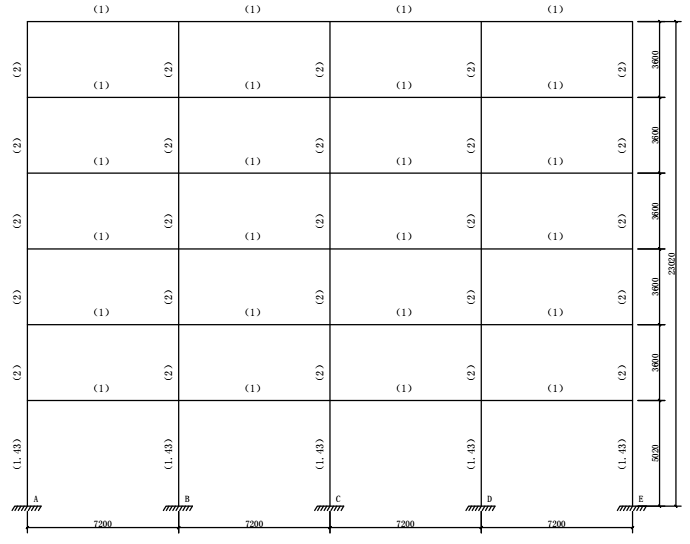
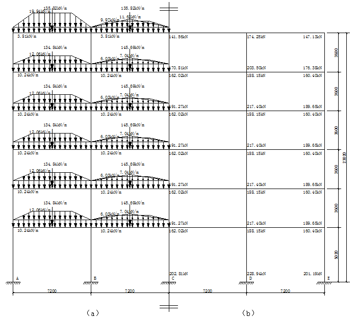
结构设计部分包括手算完成一榀框架的设计以及利用PKPM、盈建科等软件完成整体结构的设计。手算部分首先确定结构布置及结构选型;然后进行荷载统计;通过层间相对弹性转角进行侧移验算;接下来是内力计算,其中竖向荷载通过弯矩二次分配的方法计算,水平荷载通过D值法计算;内力组合则要充分考虑各种荷载之间的组合,选出控制截面的最不利内力;最后根据统计的内力进行构件设计,主体结构的计算就完成了。接下来就是利用PKPM、盈建科等软件进行结构建模、结构计算和分析、绘制相应的结构施工图。最后将手算与电算结果进行对比,分析产生差异的原因。
计算分析表明,本次毕业设计计算方法正确,分析方法合理,毕业设计任务顺利完成。
关键词:框架结构;建筑设计;结构设计;手算;电算;对比分析;
Abstract
This graduation project topic is the friendship center outpatient building design,.It is a multi-storey reinforced concrete frame structure. This design needs to carry out architectural design and structural design, complete the main structure calculation of the structure, and draw the relevant building drawings and structural construction drawings.
The architectural design part refers to relevant codes and atlas, and combines with the topic selection to complete the design of plan, elevation, section and architectural structure.
The structure design part includes the design of one frame by hand and the design of the whole structure by using software such as PKPM and yingjianke. First, the structure layout and structure selection are determined in the hand calculation part. Then load statistics are carried out. The lateral displacement is checked by the relative elastic rotation Angle between layers. The following is the calculation of internal forces, in which the vertical load is calculated by quadratic distribution of bending moment, and the horizontal load is calculated by D value method. The combination of internal forces should fully consider the combination of various loads to select the most unfavorable internal forces of the control section. Finally according to the statistical internal force to design the elements. Now the main structure of the calculation is completed. The next is to use PKPM, yingjianke and other software to build structural model, calculate and analyze the whole structure, draw the corresponding structure construction drawings. Finally, the results of calculation by hand and calculation be software are compared, and analyzed the reasons for the differences.
The result of calculation and analysis show that the calculation method is correct and the analysis method is reasonable. Graduation project tasks successfully completed.
Key Words:Frame structure; Architectural design; Structural design; Calculation by hand; Calculation be software; Comparative analysis;
目录
摘 要 Ⅰ
Abstract Ⅱ
第1章 建筑设计资料 1
1.1气象条件 1
1.2工程地质条件 1
1.2.1场地条件 1
1.2.2水文地质条件 2
1.3技术条件 2
1.4其他设计条件 2
第2章 结构布置与结构选型 4
2.1 结构平面布置 4
2.2 主要构件选型及尺寸的初步估算 6
2.2.1框架柱截面尺寸 6
2.2.2框架梁截面尺寸 6
2.2.3现浇板厚度 7
2.3 确定框架计算简图 7
2.3.1选取荷载计算单元 7
2.3.2计算简图 7
2.3.3计算几何参数 8
第3章 荷载标准值计算 10
3.1 恒荷载计算 10
3.1.1作用在框架梁上的分布荷载 10
3.1.2作用在框架梁上的集中荷载 12
3.1.3作用于框架柱上的集中荷载 13
3.2活荷载计算 19
3.2.1作用在框架梁上的分布荷载 19
3.2.2作用在框架梁上的集中荷载 20
3.2.3作用在框架柱上的集中荷载 21
3.3风荷载计算 23
3.4地震荷载计算 26
3.4.1重力荷载代表值计算 26
3.4.2自振周期计算 34
3.4.3计算底部剪力 34
3.4.4计算横向地震作用 35
第4章 框架侧移计算 37
4.1柱抗侧刚度D值的计算 37
4.2框架侧移计算 37
第5章 内力计算 39
5.1 恒荷载作用下的内力计算 39
5.1.1梁柱参数计算 39
5.1.2弯矩计算 39
5.1.3剪力计算 42
5.1.4轴力计算 44
5.2 活荷载作用下的内力计算 47
5.2.1梁柱参数计算 47
5.2.2弯矩计算 47
5.2.3剪力计算 49
5.2.4轴力计算 50
5.2.5绘制内力图 51
5.3 风荷载作用下的内力计算 52
5.3.1柱抗侧刚度计算 52
5.3.2计算层间剪力 53
5.3.3柱剪力计算 53
5.3.4计算柱反弯点高度比 53
5.3.5计算各层柱杆端弯矩 53
5.3.6根据节点平衡计算梁端弯矩 54
5.3.7剪力计算 54
5.3.8轴力计算 56
5.3.9绘制内力图 58
5.4 地震荷载作用下的内力计算 59
5.4.1柱抗侧刚度计算 59
5.4.2柱剪力计算 60
5.4.3柱反弯点高度比计算 60
5.4.4柱端弯矩计算 60
5.4.5梁端弯矩计算 61
5.4.6剪力计算 61
5.4.7轴力计算 63
5.4.8绘制内力图 64
第6章 内力组合 66
6.1 控制截面处内力计算 66
6.1.1梁控制截面处内力计算 66
6.1.2柱控制截面内力计算 70
6.2 梁弯矩调幅 74
6.3 框架梁内力组合 76
6.4 框架柱内力组合 84
6.5重力二阶效应验算 98
第7章 梁柱截面设计 99
7.1 内力调整 99
7.1.1 框架梁的剪力设计值 99
7.1.2 框架柱的内力调整 100
7.2 框架梁配筋 101
7.2.1 正截面受弯承载力计算 102
7.2.2 斜截面受剪承载力计算 105
7.2.3 框架梁附加箍筋验算 107
7.3 框架柱配筋 108
7.3.1 轴压比验算 108
7.3.2 正截面受弯承载力计算 108
7.3.3 斜截面受剪承载力计算 117
第8章 楼梯设计 119
8.1设计参数 119
8.2踏步板设计 119
8.3梯段斜梁设计 121
8.3.1荷载计算 121
8.3.2配筋计算 121
8.4平台板设计 123
8.4.1荷载计算 123
8.4.2配筋计算 123
8.5平台梁设计 124
8.5.1荷载计算 124
8.5.2配筋计算 124
第9章 柱下独立基础设计 127
9.1设计资料 127
9.2确定基础底面尺寸 127
9.2.1地基承载力特征值计算 127
9.2.2作用于基础顶面的荷载计算 127
9.2.3初步选择基础底面尺寸 128
9.2.4验算持力层地基承载力 129
9.3基础高度验算 129
9.3.1基底净反力计算 129
9.3.2抗冲切承载力计算 130
9.3.3冲切荷载计算 130
9.4基底配筋计算 131
9.4.1柱边及变阶处基底反力计算 131
9.4.2柱边及变阶处弯矩计算 132
9.4.3配筋计算 132
第10章 板的设计 133
10.1荷载设计值 133
10.2内力计算 133
10.3配筋计算 134
第11章 计算结果对比分析 136
第12章 结语 137
致 谢 138
参考文献 139
第1章 建筑设计资料
1.1气象条件
(1)全年气温:平均气温:16.7°C。
极端最高:40.3°C;
极端最低:-10.9 °C。
(2)平均相对湿度:76%。
(3)主导风向及风压:冬季为北偏东风,夏季以南风为主。
基本风压 
(4)降水和降雪:平均年降雨量 600 mm 。
基本雪压
1.2工程地质条件
1.2.1场地条件
拟建场地属长江二级阶地,场地地形起伏不大,较为平坦。场区内表层为人工堆积层,其下为长江冲洪积层。室外地面绝对标高 24.25 m。根据勘探结果和土工试验结果,场区内地层分布自上至下可分为:
1 层 人工填土:以素填土为主,黄褐色,可塑,湿~很湿,结构松散,主要由粘性土组成,夹少量碎砖瓦片等,层厚约为 0.5 m;
2 层 亚粘土:黄灰、黄褐色为主,可塑状态,局部呈软塑,很湿,含少量高岭土,少量铁锰氧化物及其结核,层厚约为 0.6m;
3-1 层 粘土:灰黄、褐黄等色,硬塑状态,湿,含灰白色团块状高岭土,铁锰氧化物及其结核,层厚约为 5.4 m;
3-2 层 亚粘土:灰黄、土黄、黄褐色为主,可塑~硬塑状态,较湿,含高岭土,铁锰氧化物及其结核,底部夹少量石英、碎岩、小碎石,层厚约为 4.9 m;
4 层 亚粘土夹碎石:棕黄、黄褐色为主,可塑~硬塑状态,密实,夹5~15%的石英砾粗砂颗粒,碎石成分为石英砂岩,矽质岩,次棱角~棱角状,约占20~40%,最大厚度为3.7 m;
5 层 亚粘土:棕黄、淡紫红色,可塑~硬塑状态,含少量高岭土,铁锰氧化物,夹个别碎石。
表1.1 场地土层主要物理力学性质指标
层序 | 年代 成因 | 物理力学性质指标 | |||||
容重γ(kN/m3) | 粘聚力 指标 Ck(kPa) | 内摩擦角标准值φk(°) | 压缩系数 (MPa-1) | 承载力标准值fk (kPa) | 压缩模量Es(MPa) | ||
1 |
| 17.3 | 30.15 | 11.2 | 0.548 | / | / |
2 |
| 19.0 | 27.58 | 19.4 | 0.384 | 140 | 4.5 |
3-1 |
| 20.2 | 91.03 | 23.9 | 0.089 | 280 | 13.8 |
3-2 |
| 19.2 | 54.70 | 18.9 | 0.281 | 250 | 8.0 |
4 |
| 19.7 | / | / | 0.214 | 350 | 14.0 |
5 |
| 20.3 | / | / | 0.214 | 250 | 10.0 |
1.2.2水文地质条件
场区内地下水属上层滞水,埋深不一,随地形起伏变化,埋藏于人工填土层中,受大气降水及地表散水影响,随季节变化。根据钻孔取水分析判定,该地下水对混凝土无侵蚀性。地下水静止水位在自然地面以下 0.1m~1.2m。
1.3技术条件
(1)材料供应:各种建筑材料供应货源充足,均可满足施工要求。
(2)建筑构配件及半成品供应条件:钢筋混凝土预制构件由构件厂供应;门窗由建设单位负责加工订货,并按施工计划供应;大批量钢筋由钢筋车间统一加工,现场设钢筋棚可进行小型钢筋加工。
以上是毕业论文大纲或资料介绍,该课题完整毕业论文、开题报告、任务书、程序设计、图纸设计等资料请添加微信获取,微信号:bysjorg。
相关图片展示:
