地铁3号线工程某混凝土箱梁桥施工图设计毕业论文
2020-04-12 08:44:16
摘 要
随着我国社会的进步和经济的发展,我国的桥梁建造也取得了很快的发展。迄今,在众多的桥梁当中,连续梁桥具有受力较好,承载能力大,桥面连续,行车条件好,伸缩缝较少,属于超静定结构,后期养护容易等优点。伴随着科技的进步和技术的革新,预应力混凝土连续梁桥得到了极大的发展,这种发展被广泛应用到公路、高速公路和城市桥梁的建设之中。
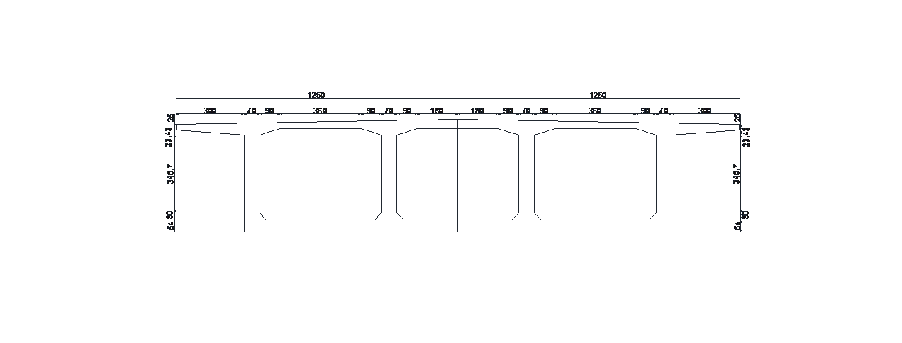
本次毕业设计54m 90m 54m预应力混凝土连续梁桥,桥梁全长198m,桥宽25m,分为两幅,截面形式为单箱单室。设计荷载标准为公路—I级汽车荷载。主梁采用挂篮悬臂对称施工。
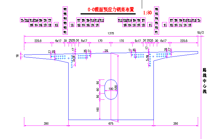
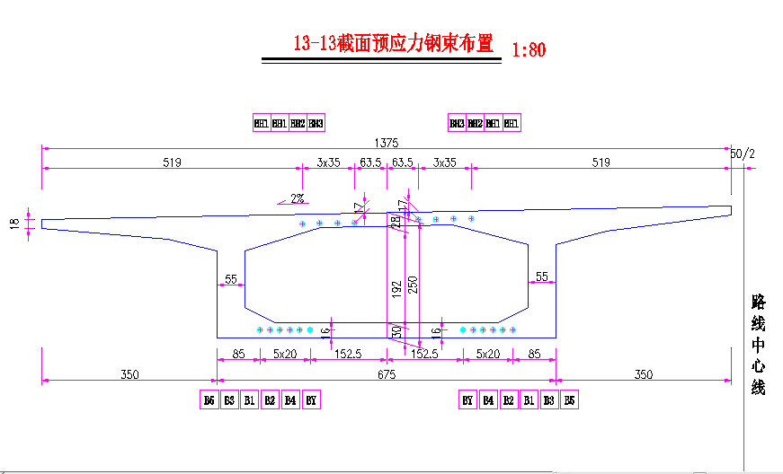
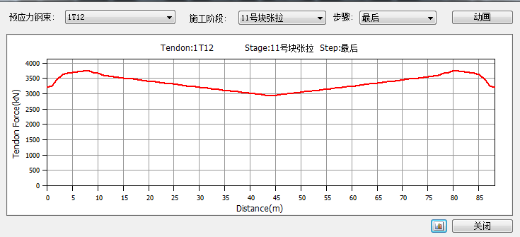
在本设计中,在设计好截面与模型的基础上,设计使用桥梁结构分析软件—Midas进行桥梁初始结构内力分析,对即桥梁的恒载、活载及徐变内力进行分析和计算,并依据内力计算结果,进行预应力钢筋数量的估算和预应力钢束的估算。然后结合AutoCAD软件初定预应力钢束的位置并布置预应力钢束布置预应力钢筋,并进行预应力损失计算和次内力计算。再对模型进行结构验算与承载能力和变形的验算,对已布置预应力钢束的模型进行应力、变形、裂缝等方面的分析验算,根据需要再去调整预应力钢束的数量和位置。最后,对控制截面进行手算以复核软件计算的结果直至所有验算项目全部通过。完成以上工作内容后,然后绘制施工图,包括桥跨布置图、施工程序图等,最后编制设计计算说明书。
关键词:预应力混凝土; 连续梁; 内力计算; MIDAS建模
Abstract
Along with the progress of science and technology and technological innovation, continuous beam bridge to 60% of the total number of Bridges in our country, the prestressed concrete continuous girder bridge with large span, and low cost, make it got great development, the development has been widely applied to the construction of roads, highways and city Bridges.
The main structure of the bridge is 54m 90m 54m three-span prestressed concrete continuous girder bridge, the bridge is 198m, the bridge width 25m is divided into two sections, the cross-section form is single box room. The main beam is symmetrical with the hanging basket.
In this design, on the basis of good design section with the model, the design uses special bridge structure analysis software initial structure internal force analysis of the bridge, the bridge dead load, live load and internal force analysis, and according to the internal force calculation, estimation of prestressed steel beam. Then the position of the prestressed steel beam with AutoCAD software and the prestressed steel beam are arranged, and the prestress loss and the internal force calculation are carried out. To model the structure bearing capacity limit state and serviceability limit state checking, for the arrangement of prestressed steel beam model of stress, deformation, fracture analysis calculation, according to the need to adjust the amount of prestressed steel beam and position. Finally, the control cross section is calculated with the result of the calculation of the nuclear software until all the items are approved. The paper indicates that the design of the section type, the arrangement of the steel beam and so on meet the basic requirements of the design calculation. After completing the above work, draw the construction drawings, including the bridge layout diagram, the construction procedure diagram, etc., finally the design calculation instruction.
Key Words :Prestressed concrete; continuous beam; internal force calculation; MIDAS modeling
目录
摘 要 I
Abstract II
Key Words : II
第1章 绪论 4
1.1 预应力混凝土连续梁桥概述 4
1.1.1 连续梁桥的主要受力特点 6
1.1.2 本桥的施工方法概要


 7
7
1.2 毕业设计的目的和意义 8
1.2.1 选题目的 8
1.2.2 选题意义 8
1.3桥型方案比选 9
1.3.1设计方案 9
1.3.2方案比选 9
第2章 设计依据及设计计算资料 11
2.1 依据规范和技术指标 11
2.1.1 设计依据规范 11
2.1.2 主要技术指标 12
2.2 地形地质概况 12
2.2.1场地底层构成及其岩土特性 12
2.2.2场地水文地质条件 14
2.3 采用的材料 14
2.3.1 混凝土 14
2.3.2 钢筋 15
2.3.3 钢材 15
2.3.4 其他材料 15
2.4 设计荷载 16
2.4.1 结构自重 16
2.4.2 收缩及徐变 16
2.4.3 温度作用 16
2.4.4 基础变位 17
2.4.5 静风荷载 17
2.4.6 挂篮自重及悬浇节段最大控制重量 17
第3章 桥跨的总体布置及结构尺寸拟定 18
3.1 桥跨布置 18
3.1.1 桥孔分跨 18
3.2 主梁截面形式与梁高拟定 18
3.2.1 主梁截面形式 18
3.2.2 主梁截面高度 19
3.3 箱梁构造与细部尺寸 20
3.3.1 顶板和底板 20
3.3.2 腹板 20
3.4 主梁横截面图和立面图 21
第4章 内力计算与组合 23
4.1恒载内力的计算 23
4.2活载内力计算 24
4.2.1横向分布系数的计算 25
4.2.2活载内力的计算 25
4.2.3计算结果 26
4.3次内力计算 27
4.3.1温度引起的内力计算 27
4.3.2徐变引起的内力计算 30
4.4承载能力极限状态的内力组合 31
4.5正常使用极限状态的内力组合 33
4.6内力组合 34
第 5 章 预应力钢束数量及损失计算 39
5.1预应力钢束数量的确定 39
5.1.1估算原理 39
5.2预应力束的布置 45
5.2.1布置原则 45
5.2.2钢束的布置 47
5.3预应力钢束与管道壁之间的摩擦 49
5.4锚具变形、钢束回缩和接缝压缩 50
5.5混凝土弹性压缩 51
5.6预应力钢束的应力松弛 51
5.7混凝土的收缩徐变 52
5.8预应力钢束的有效应力计算 53
第6章 主梁验算 59
6.1持久状况承载能力极限状态验算 59
6.1.1截面受压区高度 59
6.1.2正截面抗弯承载力验算 60
6.1.3 斜截面抗剪承载力验算 63
6.2持久状况正常使用极限状态验算 68
6.2.1正截面抗裂验算 68
6.2.2斜截面抗裂验算 69
6.3持久状况构件应力验算 73
6.3.1正截面混凝土法向压应力验算 73
6.3.2正截面受拉区预应力钢束拉应力验算 75
第7章 下部结构计算 83
7.1 桥墩计算 83
7.1.1恒载计算 83
7.1.2活载计算 84
7.2截面配筋计算 85
7.3墩柱截面承载力复核 86
第8章 钻孔灌注桩计算 88
8.1尺寸布置及荷载信息 88
8.1.1尺寸布置 88
8.1.2荷载信息 88
8.2桩长计算 89
8.3 桩基配筋计算及桩身材料截面强度验算 91
参考文献 93
致 谢 95
第1章 绪论
1.1 预应力混凝土连续梁桥概述
 可看作是一种预先
 的
的 。对
。对 施加
施加 ,既是
,既是 ,又是
,又是 所引起
所引起 。考虑到会导致相当可观的预应力损失,故必须材料才能使
 预应力混凝土获得良好的使用效果。
 梁式结构体系,在上世纪50年代前,它虽然是
 的结构形式,但跨径都在
 以下。当时主要用
 进行施工,费时费工,从而
 的发展。在50
 后期,
后期, 臂施工法施工之后,加速了它
 发展。在60年代,由于
 和
和 体系两者之间的相互结合,从而
 T型刚构,其
 100m~200m范围内。在60年代初期,对大跨度
 连续梁桥,随着各种
 的悬臂
的悬臂 法的应用,从而使高度
 施工方法代替了
 工方法,进而使连续梁桥有了很强
 的竞争力,其跨径在40m~200m
 。表1-2
。表1-2 分国外预应力
 梁桥(主跨gt;100m)的建造情况。
以上是毕业论文大纲或资料介绍,该课题完整毕业论文、开题报告、任务书、程序设计、图纸设计等资料请添加微信获取,微信号:bysjorg。
相关图片展示:
