南京某机电制造有限公司3#厂房毕业论文
2020-07-08 21:51:59
摘 要
本工程为实际应用课题,是南京某机电制造有限公司因生产需要而建设,
本毕业设计是南京某机电制造有限公司拟建 3#厂房,为两跨双坡单脊单层轻型
门式刚架钢结构厂房,跨度分别为 18m 和 15m,刚架间距 6m,平面轴线尺寸为
33m×72m,跨内各设置起重量为 5t 中级工作制电动单梁吊车 1 台。建筑总平面,示意图、初步确定的柱网布置、厂房剖面示意图见附图。
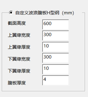
结构部分:进行结构布置,选择构件截面尺寸及材料标号。对下列结构、构件进行设计计算:围护结构设计:对墙面系统、屋面系统设计,手算一个屋面板、一个墙面板、一个墙梁、一个檩条,其余用专业软件设计。吊车梁设计:任选一个吊车梁手算,其余用专业软件设计,比较采用波纹腹板 H 型钢的优势。选取有代表性的门式刚架计算单元,确定计算简图,导算荷载,要求手算;应用专业软件对门式刚架进行设计以确定构件截面;内力分析采用软件计算;内力组合与梁柱截面设计,要求手算;连接节点设计,要求手算。
Abstract
This engineering is a practical application project, nanjing is a mechanical and electrical manufacturing co., LTD., due to the need of production and construction, this graduation design is an electrical and mechanical manufacturing co., LTD. Proposed 3 # building of nanjing, for both cross double slope single ridge monolayer light portal type rigid frame of steel structure workshop, span is 18 m and 15 m, respectively frame spacing of 6 m, axis plane size is 33 m x 72 m, each set up in the cross weight of 5 t intermediate duty electric single-girder crane 1.The general plan of the building, the schematic diagram, the preliminarily determined layout of the column network and the profile diagram of the workshop are shown in the attached drawing.
Structural parts: structure layout is carried out, and the section size and material label of components are selected.Design calculation, structure of the following components: retaining structure design: to metope system, roofing system design, hand is a roof panel, wall panels, a wall beam, a purlin, the rest of the design with professional software.Crane girder design: choose a crane girder manually, the rest are designed with professional software, compared with corrugated web h-section steel advantages.Select the representative portal frame calculation unit, determine the calculation diagram, calculate the load, require manual calculation;The door frame is designed with professional software to determine the component section.Software is used for internal force analysis.The design of internal force combination and beam and column cross section requires manual calculation.The connection node design requires manual calculation.
目 录
第一章 设计资料......................................1
1.1 工程概况.............................................1
1.2 设计内容和要求.......................................2
第二章 建筑设计以及结构的选型与布置..................3
2.1 建筑设计.............................................3
2.2 结构的选型与布置.....................................4
第三章 结构设计......................................5
3.1压型钢板的设计.........................................5
3.2檩条设计...............................................8
3.3墙梁设计..............................................11
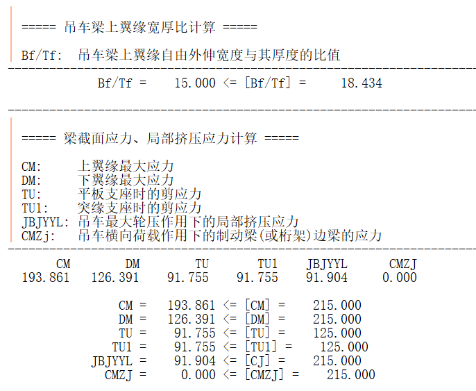
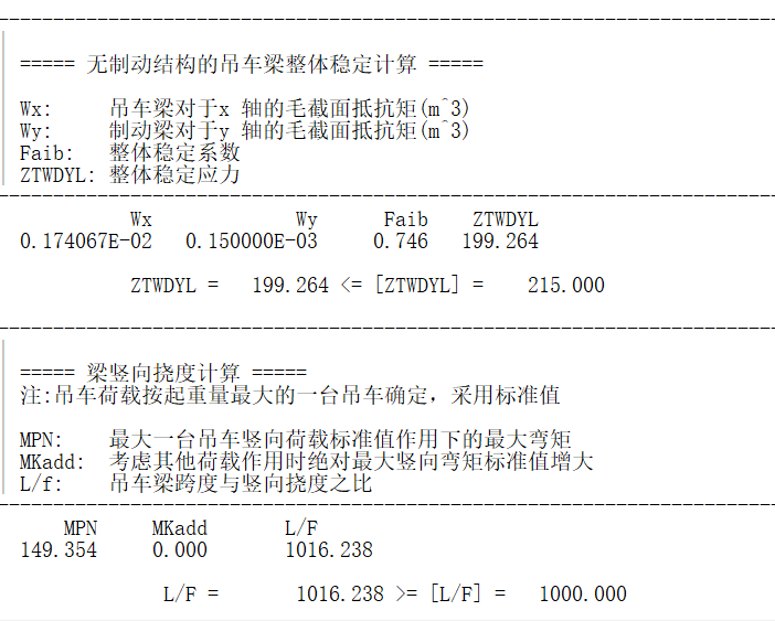
3.4工字形吊车梁设计......................................13
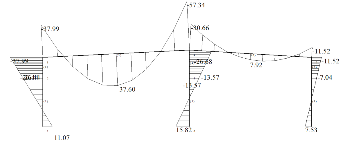
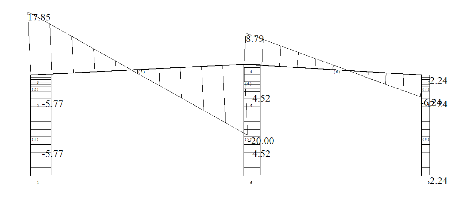
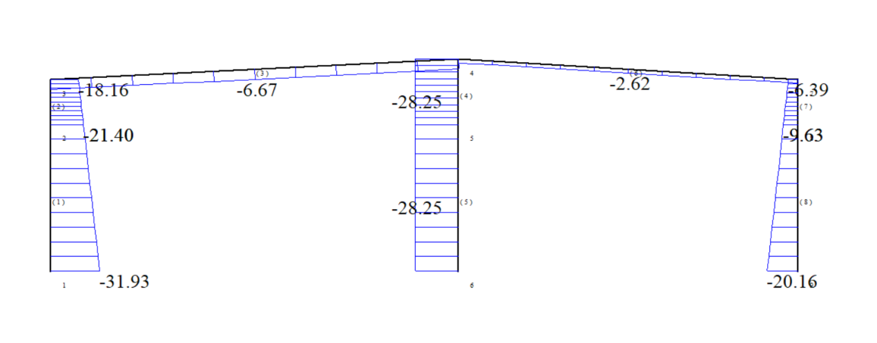
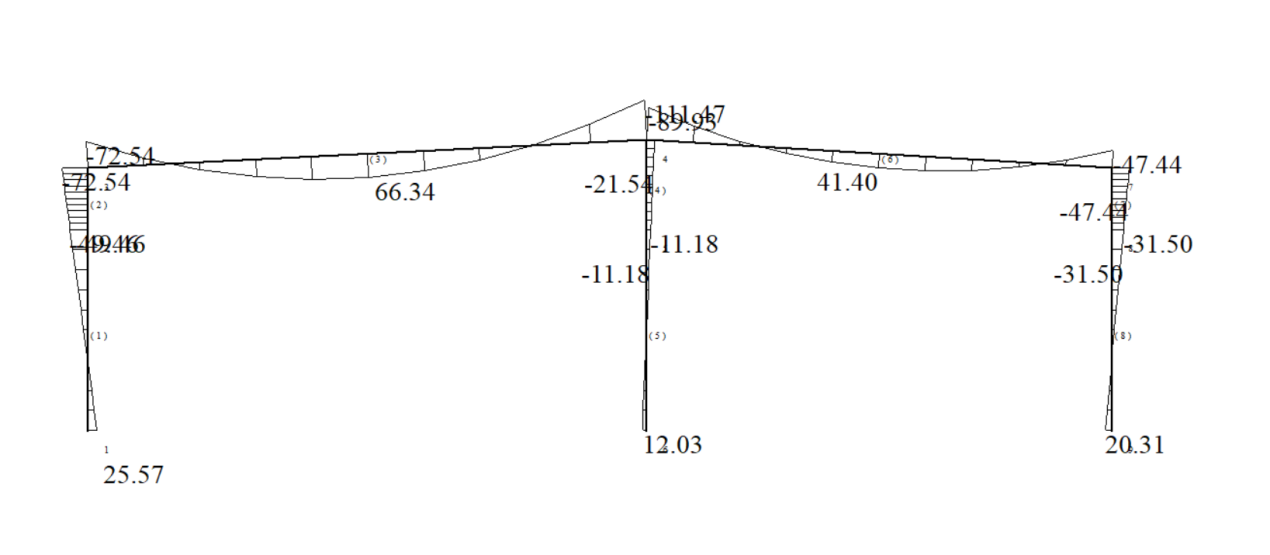
3.5刚架各个内力下的内力图................................18
3.6刚架梁柱截面验算......................................32
3.7刚架节点设计..........................................50
3.8基础设计..............................................63
第四章 工程量清单...................................67
附录.....................................................69
致谢.....................................................82
参考文献.................................................83
第一章 设计资料
1.1工程概况
1.1.1工程名称
南京某机电制造有限公司3#厂房设计。
1.1.2工程地点
江苏,南京。
1.1.3已确定的设计初步方案
本工程为实际应用课题,是南京某机电制造有限公司因生产需要而建设,
本毕业设计是南京某机电制造有限公司拟建 3#厂房,为两跨双坡单脊单层轻型
门式刚架钢结构厂房,跨度分别为 18m 和 15m,刚架间距 6m,平面轴线尺寸为
33m×72m,跨内各设置起重量为 5t 中级工作制电动单梁吊车 1 台。建筑总平面,示意图、初步确定的柱网布置、厂房剖面示意图见附图。
相关图片展示: